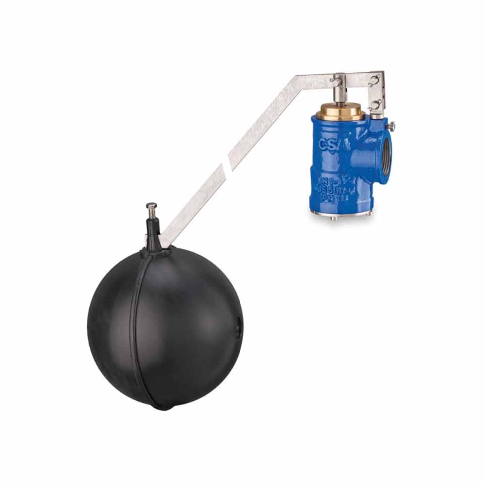
Ball Float Valves
The Flow Control Group supply a complete range of Ball Float Valves for a wide range of applications in the water, wastewater, oil and gas and industrial process sectors.
The specification and selection of a valve and its operating protocols is essential to the optimum performance of any valve. The Flow Control team have the knowledge and expertise to identify the correct valve for the desired application.
A ball float valve is designed to slow the flow rate of product being delivered into a tank, and thus reduce the possibility of a spill resulting from an overfill.
When a product flows into a storage tank, the rising level of liquid gradually displaces the air/vapor mixture present in the tank. As the liquid level rises, the displaced air/vapor is forced out of the tank through a vent or Stage I vapor recovery riser. The vent, which is attached to an opening in the top of the tank, extends via a pipe.
The ball float valve is connected to the bottom of the vent pipe or vapor recovery riser, inside the tank at the point where the pipe enters the storage tank. The valve is a short length of pipe with a little wire cage suspended from its bottom. A small hole is drilled into the pipe, near the top. Inside the cage is a hollow metal ball, about two inches in diameter.
Most of the time, this ball simply rests in the bottom end of its little cage, doing nothing. But when the tank is filled, the liquid level of the incoming gasoline, or other product, will eventually reach the ball. As the liquid level continues to rise, it will float the ball upward. Soon, the ball will reach the uppermost portion of its cage, seating itself against the bottom portion of the pipe.
When this happens, the ball essentially seals off the bottom of the pipe opening. After this opening closes, the only escape route for the air/vapor mixture remaining in the tank is the small hole drilled in the ball float valve. The mixture can’t easily get out. Something has to give. What happens is that the rate of flow of the product being delivered into the tank slows down as the
Additional information
| Design Standard | Design and testing according to EN 1074 |
|---|---|
| Pressure Rates | Pressure range: 10-16 bar. |
| Connections Water | Flanges size from DN 50 to DN 400 mm. |
| Connections | Flanges size from DN 50 to DN 300 mm. |
| Materials | Body and cover in ductile cast iron GJS 450-10. |

